There are several types of dimmers available. Most employ a triac or thyristor devices. These may be used for resistive loads, such as incandescent, cold cathode and other lights. For other loads, be sure to read to the note on reactive loads.
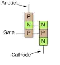
The simple electronic switch may be built using a thyristor. A thyristor is also known as a silicon controlled rectifier (SCR). It consists of 4 layers, similar to a pair of cross-connected transistors. The device has three terminals, one common, one connects the load and one the gate. The device fires when the gate is above a threshold, and remains on (i.e., conducting), until the power to the anode is removed.
PNPN structure of a SCR
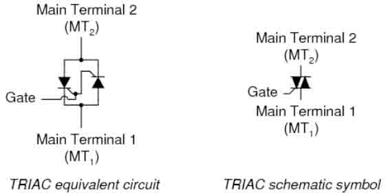
A typical dimmer circuit uses a Triac to control the amount of electrical energy passing to the load. A triac is essentially two thyristors (SCRs) combined in one package. The polarity of the signal to the gate can be either positive or negative.
Triacs are essentially used as high-speed mains switches. A phase-triggered TRIAC uses a mains trigger signal that needs to be aligned to end of each half mains cycle to trigger the 'Triac Gate' in the "on" state at a specific point in each mains cycle. This is sometimes called "firing". When the load current crosses the zero threshold, the TRIAC turns-off until triggered in the next half-cycle.
To help ensure firing takes place, a Diac is normally used to ensure a sudden increase in the Triac Gate voltage. A small capacitor (e.g. 10 nF) can be charged and the charge dumped via the diac to the Triac Gate when triggering. The switching speed of triacs is very fast and they are able to switch from fully off to fully on, typically in 1µS. For high power, it is important that a Triac fires cleanly when triggered and turns off promptly at end of each cycle.
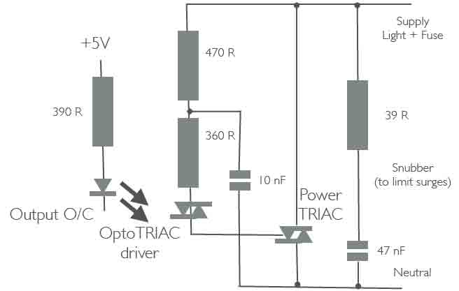
Example circuit for an open collector output.
The diac is a 2 terminal device, like a transistor without a base and acts basically like two diodes connected cathode to cathode. It is designed to have a particular break-over voltage, typically about 30 volts, and when a voltage less than this is applied in either polarity, the device remains in a high resistance state with only a small leakage current flowing. Once the break over voltage is reached however, in either polarity, the device exhibits a negative resistance.
Once triggered, the Triac relies on the current flowing through the device to keep it conducting. The Triac therefore turns-off at the end of each mains cycle. The later the device is fired, the later it starts to conduct in the cycle and hence less power is transmitted to the load.
For example, the trigger signal for 20% output is the last 20% of each half cycle (positive and negative part of the cycle). The trigger signal for 75% output is the last 75% of each half cycle (positive and negative part of the cycle). The trigger pulse must complete before the end of the half cycle, to avoid ambiguous firing in the next cycle. The output waveform therefore comprises partial cycles of the mains 50 Hz waveform.
The control voltage generated by a controller (e.g. micro computer that generates the Triac firing sequence) is usually optically isolated from pulse that is delivered to the gate of the dimmer circuit. This typically uses an opto-isolater, often in the form of a single-chip OptoTriac driver.
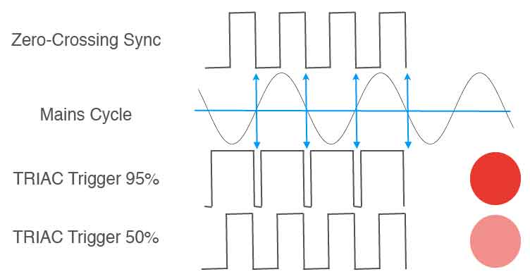
Triac driver waveform for 95% and 50% trigger.
For a mains voltage incandescent lamp, which provides a resistive (non-reactive) load, the voltage and current waveforms are almost identical. The current lags behind the voltage for an inductive load means that it is possible that the current through the Triac will not reach the threshold level of the trice before the trigger pulse ends. This results in erratic dimming behaviour. To avoid this, dimmers designed for use with wire wound transformer loads use a "hard" firing technique (e.g. using a "pulse" capacitor). This ensures that the trigger pulse is maintained for a long enough period of time to ensure that the current reaches the devices threshold level.
Triac-based light dimmer circuits chop the mains sine wave, which causes fast voltage and current changes. This results in interference that can be at MHz, and impact other mains equipment. A filter should be used to reduce this interference! The simplest form is a small capacitor (typically 20nF to 47nF) as a snubber in parallel with the dimmer circuit and positioned near to the control circuit. Note that this capacitor must be rated for this kind of application!!!
Solid state relays provide the circuitry for mains control in a simple single package. They are manufactured with either a zero voltage turn on (suitable for switching) or a random turn on, also known as instantaneous (suitable for dimmer applications). They can be either ac or dc voltage controlled. The ac version can be used for dc, which uses just half of the device.
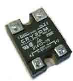
A Crydom D2410-10 Solid State Relay available in both zero-voltage or instantaenous/random switched versions. The mains load is switched on terminals 1,2 and the control is applied to terminals 3 and 4.
The smaller the chip, the lower the cost, but this also results in lower performance to surge (or overload) current is reduced, power dissipation is increased and thermal impedance is increased.
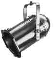
A typical load could be a theatre/stage light. The most basic of which is the PAR64. The PAR64 (or Par Can) is one of the most common and most useful lighting fixtures used today, for stage, studio and entertainment lighting applications. The fixture is lightweight and simple in design and construction. It is also economical to manufacture and easy to maintain. Tungsten halogen lamps are available in 500W and 1000W variants.
This lamp has an 8 inch lens diameter and is available in 4 different beam spreads from a very narrow spot (VNSP) to a wide flood (WFL). The beam pattern of the PAR64 is oval (not round) and is usually aligned by rotating the lamp socket at the rear of the fixture. In addition to their oval beam, PAR64's are often are usually characterized by their 'splashy' beam with a hot 'punchy' centre. They have a soft outside beam edge and produce considerable wide flare.
Because of the high degree of flare from these fixtures, the PAR64 is not commonly used for lighting applications where a high degree of control is required. For such applications, other designs of fixture are common.
Digital control can use a simple microcontroller to generate the Gate signal. The microcontroller has to first read the dimmer setting value, e.g. through the DMX512 interface (where typically the control value is an 8 bit number where 0 is a light off and 255 is fully on).
In this design a zero crossing unit will be used to detect when duty cycle from a mains supply crosses zero and switch the lamp on.
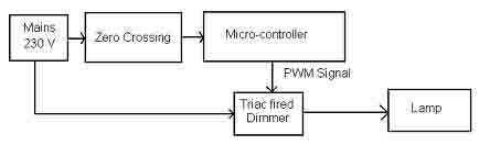
A suitable algorithm could be:
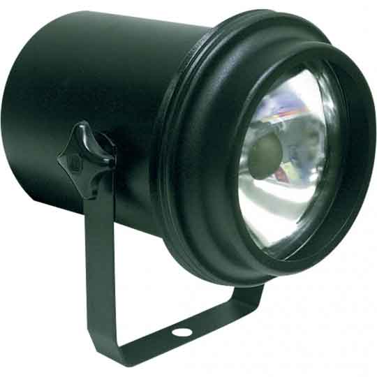

PAR-36 Lamp, with 6V Internal Transformer and PAR-36 30W VNSP spot lamp.
Care needs to be taken when supporting an inductive/capacitive load, such as equipment that incorporates a motor, transformer (e.g. a PAR-36 pinspot lamp), or semiconductor voltage convertor (e.g. LED lamp). Check the dimmer and equipment before connecting!
Caution is also needed before for strobe lights, fluorescent lights (like UV tubes), and for any fixture with internal electronics (intelligent lights, neon signs, plasmaballs etc.).
A range of professional units are available with 13A/15A inputs for UK/Europe, and 32A single or 3-phase supplies.
For a mains voltage incandescent lamp, which provides a resistive (non-reactive) load, the voltage and current waveforms are almost identical. A transformer used with low voltage lamps is highly inductive, and some forms of electronic "transformers" are highly capacitative. Consequently, the current and voltage are not in phase. For a transformer, the current tends to lag behind the voltage; this causes problems where the zero-crossing circuit is triggered by the current, instead of when the voltage passes zero. Should the current fall below the device’s threshold level it will turn off and stop conducting.
The current ’lag‘ behind the voltage for an inductive load means that it is possible that the current through the Triac will not reach the threshold level of the trice before the trigger pulse ends. This results in erratic dimming behaviour. To avoid this, dimmers designed for use with wire wound transformer loads use a "hard" firing technique (e.g. using a "pulse" capacitor). This ensures that the trigger pulse is maintained for a long enough period of time to ensure that the current reaches the device’s threshold level.
An alternative is to use a series of pulses per cycle rather than just one per cycle, resulting in a pulse-width modulation signal that chops the waveform. This is simpler in principle to the TRIAC, requiring only an insulated-gate FET or BJT to turn on and off the current in the load. With the waveform generated by a PWM circuit or in software. PWM may be preferable for dc power sources (such as LED drivers) or for inductive loads - the latter can be hard to fire the Triac at an appropriate time and control the load. Chopping at 100x the line rate is common. Higher-rate PWM may require dedicated hardware, available as standard in many microcontrollers. For a PWM-based circuit the frequency spectrum will show harmonics of the chopping frequency. Low-pass filtering is required in both cases to remove the high frequency harmonics and to prevent excessive radio frequency interference.

Chopped mains signal using a PWM signal with a 25% duty cycle. the blue signal shows the effect of filtering the choped signal (red), resulting in a near sine-wave.
You must take all normal precautions when dealing with mains voltages and large currents. If you don't know what these are, then find out before you get near these circuits.
Because controllers are directly connected to mains you must make sure that no part of the circuit can be touched when it is operating! A metal box must be earthed.
Ensure any circuit board tracks are think enough to carry the required current for the maximum load. Make sure that there is enough separation between PCB tracks for use with mains voltage.
Any choke used must handle the full load current without overheating or saturating. Use capacitors with a suitable voltage rating. Make sure that the TRIAC has enough ventilation so that it does not overheat at full load (the Triac drops about 1.5V in normal operation, therefore does dissipate some heat).
It is wise to place a fast-acting fuse or circuit-breaker in series with the load so that it will blow if the load should draw too much power from the line. The fuse can protect load and Triac.
As in resistive loads, a fuse may protect overheating of reactive loads, e.g., if a transformer core reaches saturation (which might be caused by small DC bias caused by a dimmer circuit that does not output equal power in the positive and negative cycles. This is common in simple designs intended for resistive loads). This fuse may also save any connected transformers from burning out!
See also:
Prof. Gorry Fairhurst, School of Engineering, University of Aberdeen, Scotland. (2014)