Asynchronous Slot Format
DMX uses balanced transmission.
DMX sends at 250 kbaud. This requires the time interval of a baud to 4 microseconds (1/250000). Since asynchronous transmission is used with two stop bits, there are 11 bauds in total for each byte that is sent, 4 x 11 = 44 microseconds per byte, which are sent with an efficiency of 8/11 or 73%. In DMX, these 11 bauds are called ‘slots’.
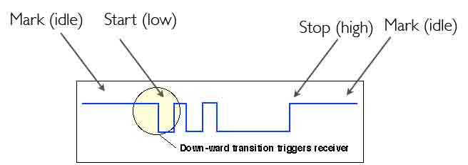
Since DMX512 is an asynchronous protocol, slots can be sent at any time that the bus is idle. When the bus is not sending it ‘idles’ in the high state. Receivers use the start bit to trigger reading the remaining bits at 4μs intervals until all 11 bauds have been read. The receiver then accepts any byte where the last two baud values were stop bits. After the second stop bit the line can either idle, (it is already high so this means do nothing) or may send a new start bit can start another byte transfer.
Note that slots do not have a parity baud.
Each data slot is identified by their position in a frame relative to the frame start. Each slot is asynchronously framed, starting with slot 1, then slot 2, etc.. The final slot is indicated by reception of a break, indicating the start of the next frame.
The Frame to frame period must be less than 1 second. This determines the minimum refresh rate.
A receiver can use one slot or many, depending on the configuration - this use must be consistent between the sender and receiver. Here are some examples:
More than one receiver can be set to the same base address. These receivers can perform an identical interpretation of the control data (e.g. if they are the same type of device, configured with the same base address) They will then also respond in the same way.
Asynchronous Slot Format
The value of all slots is sent on the line least-significant bit first.
The initial slot (position 0) will contain the start code which will inform the receiver what sort of data is going to follow and what will be controlled. For example lighting equipment will see a start code of zero and use the data in the frame to control the level of the lighting.
The remaining slots of the DMX Frame carry the control data.
Each slot carries one byte. Slot levels may therefore be between 0 and 255 decimal inclusive (00 to FF hexadecimal). A single vale could represent a dimmer control input:
e.g.
Often a combination of slot values is used.
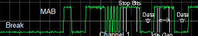
Start of a DMX Frame (showing the inverted signal to the line driver, this is the waveform of the Data- signal)
This figure shows non-default values for the transmitter parameters, setting the break and mark after break to 1355μS. It illustrates the signal for slot one with a value of 85 (33%), represented in binary as 01010101. Slot 2 and 3 contains a value 0.
The DMX specification may be logically divided into a physical and a link layer:
See also:
Prof. Gorry Fairhurst, School of Engineering, University of Aberdeen, Scotland. (2014)