DMX Receiver
Most (if not all) DMX receivers are based on a microcontroller design. The most common controller is the AVR (as used in the Arduino, and other designs), although other microcontroller (e.g., the PIC). These microcontrollers provide a set of I/O pins many can directly drive equipment> It si common for the microcontroller to support a UART on the chip, which minimises the need for external components.
Example DMX Receiver Software Architecture.
A typical basic software design for a DMX receiver contains 5 basic functions:
- Initialisation Function - This code executes when the system first starts (or the watchdog timer restarts the system). It configures registers within the microntroller (e.g., to select the clock frequency, initialise internal memory, set interrupt vectors, configure the watchdog, configure I/O ports and other aspects) and is used to initialise the data structures.
- Input Function - This is an interrupt service routine (ISR) that is triggered each time the UART receiver sees a change in the status. This could be the arrival of a “break” or the byte of data received in a “slot” from the DMX bus. The ISR can be implemented as a state machine that progresses through a series of states as it receives the set of slots within a received frame. In this case, a state variable records whether the receiver will next process a break, a slot with a start code, or the processing needs to skip the received slots until it receives the slot at the base address, or whethere it is collecting the set of consecutive slots that are to be used by a specific receiver. After receiving the required slots, the receiver continues to skip (without processing) any remaining slots until it reaches the start of the next frame. The result of this activity is that the Input Function assigns values to a shared array of slots (a receiver with a base address ‘n’, stores the value of slot ‘n’ as the first value in this array, the next the second, etc). This array is a shared data structure that is also used by the Output Function.
- Output Function - This functions uses the set of values in the shared array (updated by the Input Function). It uses these values to set the I/O value of a set of output pins. A simple design could use a one-to-one mapping of a specific slot value to a corrsponding output level on an I/O pin, or the function could be more complex, such as generating a pulse-train that performs PWM control (perhaps synchronised to the AC mains using a zero-crossing circuit to enable it to fire/trigger a TRIAC power controller). The complexity of this function depends upon what needs to be performed.
- User Interface Function - This function updates the user interface. It checks for changes to the configured address, and output to the status LEDs or display. The function could be as simple as a single flashing LED,. or might include display and a scan for input keys/switches to detect user input. This function is the least time-critical (i.e., does not need to execute at a soecific time) and therefore it is often performed as a background task when the processor would otherwise be idle.
- Watchdog Timer - A watchdog timer is provided by many microcontollers. In this use, the watchdog timer is started in by Initialisation Function. Once enabled, the Watchdog Timer can not be reset by the computer software. The watchdog timer is then periodically reset in the User Interface Function. If the watchdog timer ever counts down to zero (i.e., too much time expires since the last periodic reset), the program is assumed to have crashed. The watchdog timer in the microntroller then automatically reinitialises the hardware and then calls the Initialisation Function. This provides robust operation, even when there are software or communications errors.
The state machine described above can be implemented in an algorithm below provides a flow chart for the Input Function. It receive a DMX break, and the the slots in a DMX Frame to create a set of DMX values (stored in the shared byte array DMXField[]). Execution is triggered as an Interrupt Service Routine (ISR), for each byte (or status change) received from the UART.
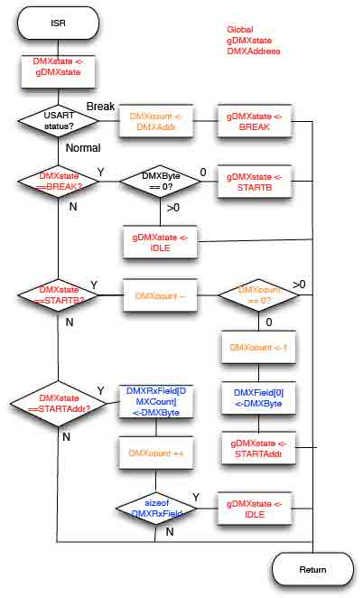
The following states are noted:
gDMXState is a global variable used by the Input Function. This is used to store the current receiver DMX state.
DMXcount is a variable that is set by the User Interface Function to the base address used by the receiver.
DMXcount is also later re-used to count the received number of bytes within the DMXField.
DMXField indicates the number of bytes that the device needs to collect from the DMX Frame.
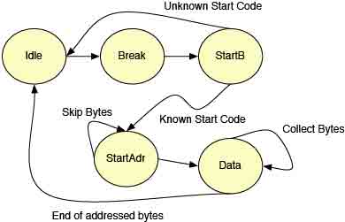
This algorithm cycles through 6 internal states to process each DMX Frame:
- The Input Function is initialised to the IDLE state, by the Initialisation Function. The Input Function waits for an interupt indicating next Break to be received by the UART. The Break is followed by a Mark-After-Break (MAB) period.
- After a Break is seen, the receiver prepares toi receive a new DMX Frame. The receiver enters the state DMXBreak. The global DMXcount variable is initialised to the value of the receiver's base address (e.g., previously read by User Interface Function by reading the value from a parallel input port connected to a DIP switch). It then waits for the first slot to be received.
- When the first slot is received, an interrupt triggers the receiver to check the UART receive data register (UDR). The value in the data register corresponds to a slot that carries the DMX Start Code. If the
DMX Start Code is unknown (i.e., the receiver has no functionto process this type of frame) the Input Function immediately returns to the IDLE state. (This skips all remaining slots within this DMX Frame.)
- If the start code is known (e.g., a zero valeu start code indicates the DMX Frame carries control data) the Input Function moves to the STARTB state. The value of the received slot is not used further.
- When each following slot is received, an interrupt triggers the Input Function. This reads and ignores the data in each slots, until the count of the number of read slots reaches the configured base address. Each interupt the global DMXcount variable is decremented (counting down).
- When the global DMXcount variable reaches zero, the Input Function knows that it has found the slot at the base address, it then enters the STARTAddr state. It stores the slot value from the User Data Registeer as the first byte in the receiver's shared array (DMXRXField) and now enters the DATA state.
- Interrupts in the DATA state, collect the value of a set of consecutive slots by each time reading the User Data Register and storing in the DMXRXField. The receiver remains in the DATA state The variable DMXCount is incremented after each of these slots are colleted, until the sizeof DMXRXField is received. This indicates that all the required data has been collected. .
- When all slots have been collected, the Input Function transitions from the DATA state to the IDLE state. This takes no action for the interrupts generated by further slots until it is interrupted by a Break. This causes any remaining slots within the DMX Frame to be skipped until the start of the next DMX Frame.
State Machine for an example DMX Receiver.
Waiting of the DMX Frame to receive the 1sts slot at the configured base address: A receiver skips the number of slots after the Start Code, corresponding to the configured base address. (e.g. for a base address of 8 the receiver skips the first 7 slots). After finding the base address, the receiver extracts a set of contiguous slots (bytes) from the DMX Frame.
Receiving multiple slots to represent values larger than one byte.
The Output Function can be designed to use a number of consecutive slots to realise a 16-bit, 24-bit, 32-bit or other size of value that can be used by the output function. However, care needs to be taken that this data is read consistently by the Output Function, to avoid issues when the values change in later DMX Frames and are updated by the Input Function. Consider a 2 byte value, where the Output Function reads the first byte from the shared receive array (part of an already recieved DMX Frame), and the Input Function then updates the value of the second value (from the current DMX Frame). This would result in an inconsistent value when the two bytes are combined (becaiuse it combines one value from one DMX Frame with a value from a later DMX Frame). A solution is to use semaphore signals between the Input Function and the Output Function to coordinate access to the shared array.
See also:
- Recommended Practice for DMX512, 2nd Edition incorporating USITT DMX512-A and Remote Device Management - RDM, 2012 (available from PLASA).
Prof. Gorry Fairhurst, School of Engineering, University of Aberdeen, Scotland. 2023