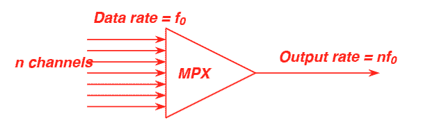
Simple diagram of a multiplexer
Multiplexing is the term used when the content of different channels is combined for transmission over a single transmission stream (link). The usual method is to take values from each of a set of inputs and then assemble the samples into a frame. For example, a time division multiplexer (TDM) that combines data from n channels onto one common high speed bearer. Each channel sampled, and then value sent at rate f0 Total transmission rate n x f0. Such methods have been used in a digital since the mid 1980s.
Simple diagram of a multiplexer
Note: In the early days, cable bandwidth (limited by capacitance per metre) was a major obstacle to high speed communications. The pioneer Harry Nyquist established a rule that a sample rate of twice the bandwidth is required for a band-limited signal.
To allow the receiver to demultiplex, a sender needs to identify the start or each multiplexing frame and the size of the data from each channel. Synchronisation is important to allow a receiver to identify the start of frame and remain in synchronisation with the sender.
One simple way to provide a synchronisation mark is to insert a special sequence in the serial data stream. to mark the start of each frame,
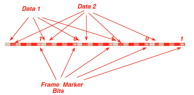
Using a frame marker to identify the start of frame.
A frame market may consist of some probabilistic unique word (i.e. set of binary bits not expected to occur frequently within the data stream, inserting the same pattern into the start or each multiplexing frame. This allows the receiver to search for this marker to acquire synchronisation. Once found, the receiver can continue to verify that the marker occurs with the correct value in the expected position at the start of each frame. This method is very simple to implement, although the method is usually extended to allow a small number of synchronisation failures so that it is robust to corruption of the frame marker bits. One drawback of this method is that a sizeable number of overhead bits are consumed in each frame to send the frame marker.
A distributed frame marker can achieve good robustness to corruption, with reduced overhead. This scheme creates a frame alignment word that is longer than the number of bits allocated as a marker in each frame. The sender inserts a different pattern from the frame alignment word into the frame marker bits each time it sends a frame. This causes the value of the frame marker field to not be constant from frame-to-frame, instead it follows some preset pattern determined by the length of the frame alignment word.
Another alternate method is to use a physical layer exception condition - such as a break sequence or loss of carrier or illegal bit pattern to serve as a marker for the start of each frame.
Since communication is usually unidirectional, the same signal may be receiver by multiple demultiplexing receivers. In this case each demultiplexor must independently synchronise its received stream to the TDM signal sent by the multiplexor. It is not essential that every receiver uses all the channels in the multiplex frame. In a multipoint application, it is quite common for different demultiplexors to extract different groups of channels. SDH/SONET is an example of such a system in the field of telecommunications and DMX 512 is an example of such a system from the entertainment industry.,
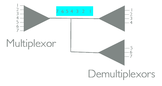
Multipoint TDM showing two demultiplexors extracting independent sets of channels from the multiplex.
Multiplexing has many advantages over a system that uses one wire per signal:
The DMX-512 specification provides a frame-based multiplex that may support up to 512 channels over a single serial stream comprised of 8-bit slots (i.e. 8 bits/channel). The start of each DMX frame is prefixed by a "break", followed by a single control slot. Following this, each slot is asynchronously framed in an 8 bit character, starting with slot 1, then slot 2, etc.. The final slot is indicated by following this with a long idle period after the slot.
Prof. Gorry Fairhurst, School of Engineering, University of Aberdeen, Scotland. (2014)