Universal Asynchronous Receiver/Transmitters
Universal Asynchronous Receiver/Transmitters implement logic
to serially transmit and receive asynchronous signals.
These are commonly available as separate chips, but are also
often integrated in microcontrollers.
At the typical baud rates used for short range asynchronous communication,
they can alternatively be implemented in software.
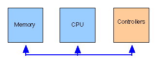
On the one side, a UART can be interfaced as an I/O controller to a computer bus.
On the other side, a serial line driver provides the physical layer connection to the cable.
The choice of driver chip depends on the voltages/current used to represent the signal on the cable
and also the baud rate to be used.
UART Operation
Each data byte to be sent is typically loaded in parallel into the transmit FIFO from the microcontroller bus. This FIFO is often double-buffered, meaning that a new value can be written in parallel from the bus; while at the same time one current byte is being shifted out by the transmit (Tx) clock (clocked from the transmit baud rate generator).
The Tx buffer relaxes timing requirements for the microcontroller while still allowing it to send continuously (double buffering). A status flag is used to signal that there is space for more data. If the sender fails to send fast enough, a transmit under-run simply results in idle time between asynchronous slots.

Serial Transmission
In asynchronous transmission, each byte is preceded by a start baud and followed by one or more stop bauds. The first baud placed on the wire is the start baud, followed by the least significant data bit from the byte being sent.
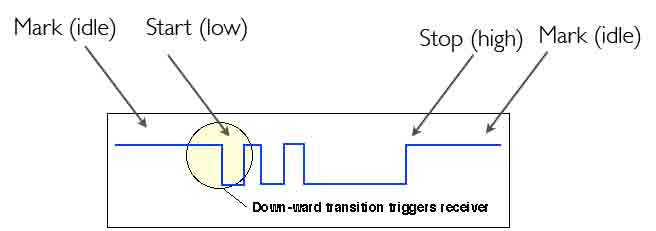
An Asynchronous byte transmission (shows the unbalanced line or Data+ signal of a balanced transmission line).
Serial Reception
The receiver does not run continuously, instead it is started by detecting the edge (a transition from idle) indidcating a start baud. This triggers reception of the slot/character using a shift register clocked by the locally generated receive clock at the same nominal baud rate that was used by the transmitter.
This is shown below:
 The transition from the idle state triggers the UART at the receiver to start reception
The receive (rx) clock is normally generated using a local stable high rate clock, frequently operating at least 2 times the intended data rate, as shown above this can be used, to find the size of a half-bit period, and align the timing with the mid position of the start bit.
The number of bauds to be converted is the number corresponding to one half the original baud period, 8 high frequency clock cycles in this example using a 16x baud rate reference). From there the centre of the successive bauds are located by counting bauds corresponding to the original data speed (16 cycles per baud in this example).
After 11 clock cycles (assuming 8 bits of data, 2 stop bauds, no parity), the contents of the Rx shift register is checked. Only data that are bounded by the correct start and stop bits are accepted, i.e. where the stop baud is one (or the two bits are both 1). Valid bytes are passed to the receive FIFO for processing by the attached computer.
There are several errors that could result in corruption, and which are recorded in the UART status register(s) - e.g. transmitter overrun, receiver underrun, bit errors, timing errors, and signal breaks.
The break sequence may be used by the receiver to detect when the cable breaks, or in the case of DMX 512, to detect the start of a frame.
First-In-First-Out (FIFO) Buffers
The RX FIFO seeks to avoid received data over-run which owuld occur when the microcontroller can not service the UART promptly. Since receive overruns will result in loss of data, this is usually much more important than avoiding underrun of the Tx. Received data would be missed if it was not buffered until read by the microcontrollwe. Most UARTs therefore set a status overrun flag in their status register to inform the connected computer that data has been lost. A deeper receiver FIFO is often needed to avoid overrun of the receiver (e.g. depth 4, which is common).
Baud Rates
Most UARTs require an external clock signal (square wave signal), often this is derived from a small crystal oscillator.
In general, the supplied clock rate will be of too high a frequency for use as a baud rate, the clock frequency may however be easily reduced using a succession of frequency dividers (each a flip-flop wired to divide the input clock by 2). The divider chain generated a set of baud rate clocks for the sender and receiver, although this does not allow arbitrary selection of the baud rate, a close baud rate can usually be found, and fortunately asynchronous framing does not require accurate clocks.
Asynchronous communications is often used to support character-based applications that use the ASCII character set, but can be used to transmit any binary value.
Matching the Transmit and Receive Baud Rate
If the receiver baud rate is different to the sender rate, the clocks will slip in time (phase) relative to one another, the more bits since the start of the byte, the bigger the slip, until finally one bit will not be sampled (or will be sampled at the edge of the waveform, where the signal is weaker.) If observed over a sufficiently long period will result in a receive error.
Consider a link operating at 9600 baud.
B= 1 baud = 1/9600 = 1.04 mS 1 slot = 11 baud (assuming two stop bauds).
A sender at this baud rate starts the last (msb) data bit of the slot at 8*B S after the start bit, i.e. at 8.32 mS. The msb bit is completed at 9*B S after the start bit, i.e. at 9.36 mS
A receiver with a baud rate also set to 9600 bps, samples the last baud at a time 8.5 *B µS after the start baud has been seen = 8.84 mS. This results in the received baud being sampled at the centre of the baud period, exactly as we would have hoped.
Now consider what would happen if the transmit baud clock was just 2% different in frequency from the receiver baud clock. The 2% lower sender rate results in the last baud of a slot starting at 8*B*.98 and ending at t 9*B*.98. We already know that the receiver will sample the baud at 8.84 mS, so this results in sampling just at the end of the last baud period, rather than at the centre of the baud, in theory this could be OK (i.e. the bauds would be correctly received), but it could increase the probability of a bit error if there was a degraded signal, since practical line drivers limit the slew rate and the receiver is not sampling at the centre of the baud. In general, a receiver will work with a receiver baud rate that is 2% or less different to the sender baud rate.
However, a larger difference will clearly not work. A 10% difference would result in the receiver failing to sample the final baud - resulting in corruption of the data (it would sample after the last baud has been received).
UART Configuration
The setup of a UART is controlled by a set of configuration registers written via the PC bus. This set parameters include:
- Interrupt and Status modes.
- Transmit Format:
- Baud Rate Registers configure a divider for the Tx baud rate generator.
- Number of Tx data bits
- Number of stop bauds
- Parity (Odd, Even, None)
- Transmit Format:
- Baud Rate Registers configure a divider for the Tx baud rate generator.
- Number of Rx data bits
- Number of stop bauds
- Parity (Odd, Even, None)
See also:
Prof. Gorry Fairhurst, School of Engineering, University of Aberdeen, Scotland (2024).