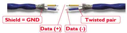
The Shielded Balanced Cable
DMX uses the EIA-484 standards with a shielded twisted pair cable (with 2 conductors/wires in a pair). This cable forms a balanced transmission line. Physical connection to the cable is specified to use a 5-pin XLR connector. Pins 1,2 and 3 of the connector carry an EIA-485 signal. This connector permits a second optional twisted pair of data conductors. Many designs use a 3-pin XLR connector instead of the standard 5-pin connector.
The Shielded Balanced Cable
The cable used in DMX-512 has the following electrical properties:
The maximum number of receivers that can be placed across a single length of EIA-485 control bus (ie. a segment) is determined by the receiver input resistance. The input impedance of 12 k Ohms restricts this to 32 receivers on a single bus. (32 parallel receivers have an overall impedance of 376 Ohms, safe for a cable of length up to 300m.)
Equipment to be connected to the DMX cable typically has both an input and output XLR connector,respectively using a male and female socket. The male and female sockets on each receiver are wired together so that the electrical signal passes straight through the equipment, and the shield is continuous. This ensures that the bus works even if any specific piece of equipment is not powered.
The receivers on a bus are connected together using cables with one make and one female XLR plug. These cable are wired so that pin 2 connects to pin 2, pin 3 connects to pin 3. The shield (also known as a shield) is wired to pin 1 at both ends of the cable.
Male Female
Pin 1 (screen)----------------------------- Pin 1 (screen)
Pin 2 (Data -)----------------------------- Pin 2 (Data -)
Pin 3 (Data +)----------------------------- Pin 3 (Data +)
Pinout of 3-pin and 5-pin XLR connectors (pins 4,5 are usually unconnected - but can be connected straight through 4 to 4 and 5 to 5).
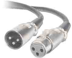
Male and Female 3-Pin XLR Connectors
Note on Grounding: It is important to only earth one end of the bus to avoid ground loops. Receivers must not connect the signal shield/earth to their local ground. This could otherwise result in a ground-loop. This could add noise to the received signal.
For some uses, DMX-512 optionally allows the line conductors at the transmitter to be referenced to the ground level, but then requires that the total resistance to ground is less than 20 Ohms. Professional interfaces isolate the Data conductors using opto-isolators, this is best practice.
Lengths of DMX cable can be plugged together end-to-end up to the maximum permitted cable total segment length. Since DMX operates at a baud rate of 250 k baud, the EIA-485 standard suggests a maximum total segment length of 300m.
Each receiver add a load on the cable. DMX allows up to 32 receivers conencted to the cable. Low resistance cables can be used to drive much greater distances (up to 1000m) when there is a sender and only a single remote receiver.
Cable terminations are important for consistent operation.
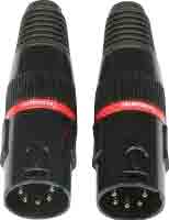
3-pin and 5-pin XLR Terminators for DMX-512
A transmission cable has a characteristic impedance that is the equivalent resistance of the cable if it were infinitely long, resulting from the cables capacitance and inductance as the voltage propagates along the cabke length. When a cable is cut to any length (or lengths of cable added to the cable segment) and terminated, measurements will be identical to the value obtained from an infinite length cable. (This is different from loss from the dielectric separating the two conductors, and the resistance of the conductors.)
To avoid an impedance mismatch (i.e.signal refelections from the open end), the bus termination must match the characteristic impedance of the cables. The simplest terminator consists of a resistor with resistance that matches the cable characteristic impedance.
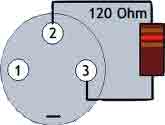
The cable used by DMX has a characteristic impedance of 120 Ohms. A DMX terminator therefore must have a resistance of 120 ohm +5%/-10%. This terminator is placed between Data+ and Data- at the end of the cable (at the end furthest from the transmitter). This could simply be a male 5 pin or 3 pin XLR plug with a 120 Ohm resistor soldered across pins 2 and 3. A more sophisticated terminator incorporates a surge suppressor as well as the resistor.
In the case where the transmitter is not at one end of the cable, then both ends of the cable need to be terminated (this is required for RDM).
Since the termination resistance is a nominal 120 Ohms and the signal voltage is 5V, the power rating of the required terminator resistor is v^2/R = 5^2/120 = 25/120 = 0.2W.
Resistor and cable tolerances, among other things, can result in mismatches between the cable and termination impedances. This will result in signal reflections that increase the noise and could ultimately lead to corruption of data. Similar to radiated emissions, the higher the frequency components and the longer the cable, the more likely it is that reflections will affect the reliability of transmission.
A repeater can be used to divide the control network into multiple cable segments (each segement is terminated at the end). This allows an increase in the total distance that can be reached by the control network and allows a network to support more than 32 receivers when using multiple cable segments.
The primary reason for the DMX specification using a 5-pin XLR connector for DMX cables was to avoid confusion with audio XLR cables that also use a 3-pin connector. Cables that are intended for use in audio systems (such as microphone cables) often have a 3-pin XLR connector and use balanced cables. However, these cables do not have a specification that matches the requirements of DMX.
Audio signals extend to only a few 10s of kHz, and therefore audio cables often attenuate signals at higher frequencies. This can distort the DMX signal (resulting in attenuation and "ringing"). The result is that these cables provide insufficient signal strength for long cable runs.
Audio cables also do not typically include a shield, since they are not impacted by signals above 100 kHz. This makes them also more vulnerable to radio interference
Some other types of balanced cables can be used to support DMX-512 (e.g., permanent installed wiring): Category 5 UTP, Category 5 Shielded UTP STP/FTP, Category 6 UTP and Category 6 FTP, S/FTP, S/STP and Category 7 S/FTP, S/STP.
Some applications demand specific types of cables, e.g. a cable could also combine DC or AC power conductors within the outer protective coating. Specific applications can also require cables with an armoured shield (steel wires wrapped around all the conductors inside the protective coating) to protect the cable from accidentially being cut (this type of cable is less common).
The DMX specification can be logically divided into a physical and a link layer:
See also:
Prof. Gorry Fairhurst, School of Engineering, University of Aberdeen, Scotland. (2018)