PoE provides a way to connect IP-devices to a network without requiring a separate power connection. Examples of use include powering a Wireless Access Point (WAP), sensor, Voice over IP (VoIP) phone, display monitor, point of sale (POS) outlets, etc. In these cases, PoE removes the need to provide a separate power cable, while in some cases it also enables network control of the power supply to the remote endpoint. This saves money in the materials used and the time taken to install.
Power is supplied over two or more of the differential pairs of wires found in an Ethernet UTP cable and comes from a power supply within a PoE-enabled networking device. The IEEE standards for PoE require CAT5 cable, or better, for high power levels but allow using CAT3, when less power is required.
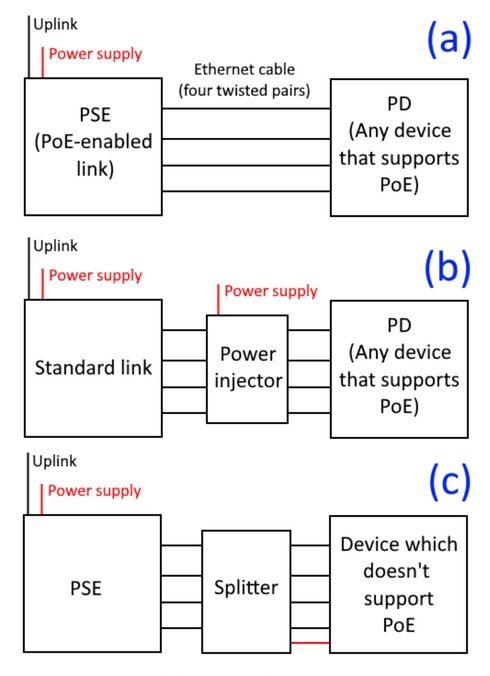
A PoE system comprise two parts: the Power Sourcing Equipment (PSE) and the Powered Device (PD).
Block diagram of power over ethernet equipment showing the PSE and PD, showing (a) endspan delivery; (b) midspan with PoE Injector; (c) midspan with PoE Splitter
Operation of PoE
A PSE detects whether a port is attached to a PD to determine if it needs to supply power, and how much power is needed. This also detects if a PD has been disconnected, which results in disconnecting the supply to the device. The physical layer mechanisms at a PSE can characterise the power demands of the individual PDs connected to each port and thus manage power delivered by the PSE. This is sometimes called Active Power, because the supply is conditional on a suitable device being present at the remote end of a cable.
To determine whether to supply power to a device and how much, the PoE standard implements a discovery process that includes the detection of a PD, classification, start-up, operation and disconnect. This procedure is the same for the different types of PoE standard.
1. PD Detection
The detection period is a vital safety feature of the standard since PoE switches can also be connected to devices that do not support PoE and where suppling power could result in significant damage. Therefore, the PSE supplies a low current-limited voltage (<10V) to detect the 25kOhm common mode termination, the signature resistance, required in each PD. This detcts that a valid PD is connected.
2. Power Classification (optional)
When a PD is detected, a PSE can optionally determine the power class of the PD, by measuring how much power the PD requires. 10ms is first allowed for the levels to settle before starting this stage and is completed within 75ms to limit power dissipation. A series of tests are thnen used to finally determine the voltage and current to be output by the PSE. There are different power classes that can be selected, The signature resistance of the PD is used in all cases as an initial test. A series of pulses can be used to identify higher classes of PD. Class 0 (15.4W) is the default for all PDs that do not support classification.
A method using Link Layer Discovery Protocol (LLDP) frames is specified in IEEE 802.3bt. This can also used between the PSE and PD allowing the PD to send MAC frames to a multicast group that are received by the management interface of the PSE. These multicast link frames carry a range of information that identifies the PD and also allows more control of the power supply, enabling higher power classes. After a PSE receives a LLDP frame from a PD device, the PSE allocates the corresponding power to the PD device and then also announces this as the PSE allocated power value of the PF in the LLDP frames that it sends.
3. Start-Up
An FET switch inside a PD ensures that the PD only starts to draw power once the detection and classification period is completed. In the start-up period, the PSE switches from low to full voltage (44-57V). This increase is gradual, avoiding a sudden rise in voltage that would add high frequency components that might otherwise introduce noise on the data transmission.
4. Power Supply
The PSE supplies a voltage in the range between 44 and 57V offering a minimum power of 15.4W. During normal operation, the PSE constantly monitors the current at the active ports to detect power overloads, short circuits or other scenarios that would require power to be shut off. Should any of these scenarios occur, the PSE will disconnect power from that port and the discovery process starts over.
There are three current limits:
5. Disconnect
When a fault is detected, or the PD removed, the supply power to the port needs to be removed within 300-400ms. The 300ms is a lower boundary to prevent power shut off due to random fluctuations.
The 802.3af standard also allows a PSE to use AC signal to determine whether to disconnect: In this case, the PSE injects a small AC signal in addition to the DC operating voltage and the port impedance, indicated by the returned amplitude of the AC signal, is measured. If no PD is present the impedance is high and amplitude would be reflected in full.
After performing a disconnect, the PSE keeps a port disconnected for at least 2 seconds.
Physical Layer Cable Connections
There are three standardised methods for supplying power by a PSE over a UTP cable. These are:
Note both modes A and B are supported for 1000BT: the key difference is which pairs are used for power transmission. All PDs must be able to support both modes to be compliant with the standard. PDs are polarity insensitive: It does not matter which of the pairs form which side of the DC supply. PoE continues to work when the polarity of the DC supply is inverted when using a crossover UTP cable. This is implemented by using a diode bridge in the PD.
Standards for Power Delivery
Standards for in-line power have been defined by the Institute of Electrical and Electronics Engineers (IEEE). The original IEEE 802.3af-2003 standard for PoE as introduced in 2003. It supplied up to 15.4W of DC power (minimum 44 VDC and 350 mA) to each device. Only 12.95 W is assured to be available at the powered device (PD) allowing for some power dissipation in the cable (as heat). In 2009, IEEE 802.3at enabled higher power PDs 25.5W (at 100m range) and provides full compatibility and inter-operability to existing 802,3af compliant PSEs and PDs. Improvements were added in 2016 in IEEE 802.3bu standard and IEEE 802.3bt in 2018. Types 3 and 4 where introduced in the IEEE 802.3bt.
IEEE Standards
802.3af
802.3at
802.3bt
See also: